Erik Engebretsen and George Chearswat: 2007
Projectiles
Motion with constant acceleration in a fixed direction is known as projectile motion described as a parabolic, if air resistance can be neglected (figure 1). Under these conditions, two balls thrown at the same initial vertical velocity will reach the same maximum height. The ideal launch angle for maximum range on level ground is 45°. The formula to calculate range without air resistance is:
Air resistance reduces the horizontal component of velocity
over time. There is little effect on the vertical component.
This causes the trajectory to become asymmetrical (no longer a
parabola).
Research question
By what factor does the ideal launch angle for maximum range change in the presence of significant air resistance?
Hypothesis
It is expected that the ideal launch angle for maximum range will be less than 45º. This prediction is made based on the knowledge that air resistance has a greater effect on the horizontal velocity. At a lower angle, there would be less effect of air resistance and the ball would achieve a greater range.
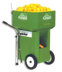
A tennis ball launching machine was set-up on a cleared court with a colored backdrop. A video camera was set-up with a view perpendicular to the path of the balls, so that a range of 15 meters was captured on the video. The ball machine was set to fire the balls at around 10 m/s which was held constant, the ball oscillation control was turned off to ensure all the balls remained in the same plane throughout their flights, and the back spin/top spin function of the machine also was turned off to reduce systematic errors from excessive spin. The camera was turned on and three balls were fired at a low angel of elevation. The angle was increased and three more balls were fired. This process of increasing the angle and firing three balls was done for 9 different angles of elevation.

Fig 3 - the ball launcher.

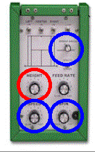
Fig 4 - the control pad. Oscillation control, height control, speed control, and spin generator.
The controls for oscillation, speed, and spin (blue circles) were not changed for all trials of the experiment. The height control (highlighted in red) was the only independent variable. It was changed for each set of three launches.
The range, initial horizontal velocities and initial vertical velocities were measured by plotting the trajectories frame by frame in Logger Pro to find the angle of elevation and the maximum range.
Data
Initial velocities were found by using video analysis in Logger Pro. Uncertainties were estimated as half of the range of each of three trial values.
Initial vertical velocities were found by finding the slope of a straight line fitted to the first four points of the Y displacement versus time graphs. A sample graph is shown at right.
Initial horizontal velocities were found by finding the slope of a straight line fitted to the first four points of the X displacement versus time graphs. A sample graph is shown at right. Note the very small change in the horizontal velocity with time.
Initial velocities, ux and uy, are listed in table 1 for three trials, at each of nine angles of elevation.
The ranges, measured from the trajectory plots in Logger Pro, are listed in table 2. The ranges are consistent for each elevation setting to within ± 0.2 m, where the error is given as half the range.
Analysis
The averaged initial velocities, the predicted ranges (without air resistance) and the measured ranges are listed in table 3.
The predicted range is plotted against the measured range with errors in graph 3. The data is a good fit (within errors) to a straight line through the origin. If the predicted and measured ranges were identical the slope of the line of best fit would be 1.0. An extreme line has been added with a slope of 1.0. Inspection shows that the slope of the line is 0.96±0.04 and there is no significant difference between the measured and calculated ranges.
The actual ranges with air resistance and predicted ranges without air resistance are plotted against the angles of elevation in graph 4. The curve fits for predicted and measured ranges are again both good fits within errors to the combined data sets. There is no evidence that there is a significant difference between the measured and predicted ranges.
The ideal angle of launch to achieve maximum range was, (from graph 4) 42±5°. Within errors, this value does not differ from 45°, the angle for maximum range with no air resistance. The research question has not been answered. Air resistance has been shown to be an insignificant factor in determining the range of the tennis ball in this case. The errors are large, and due to the following factors.
The trajectories of balls lanched by the machine on a particular setting were inconsistent. For this reason, averaging the initial velocity components for three trials at the same setting was unsatisfactory.
Since the balls were launched by a spinning drum it is not possible to launch them without some spin that will affect the trajectory.
The inconsistencies could have been increased by launching used tennis balls because they were readily available. Some were more worn than others. In professional tennis matches, the balls are changed every six games. The balls used may have been anywhere between two years and one week old, causing variability in the aerodynamics of the balls, and in the launcher/ball interaction.
In spite of selecting a calm period of the tropical day, wind could have contributed to the errors, since even a slight breeze altered the trajectory of the light tennis balls, sometimes propelling them farther, and at other times swaying them to the side. To eliminate the errors that were due to using worn tennis balls, all balls in future should be new, and of the same brand. Any differences betwen balls would be minimal.
To overcome the inconsistency of the tennis ball machine, and to ensure that all balls are launched without spin, a more consistent method of launch must be found. The balls also need to be launched with higher initial energies, and a much greater ranges, so that air resistance has a more pronounced effect.
To eliminate the wind factor, the experiment could be conducted indoors, inside a walled gymnasium, but this is impractical because of the larger ranges required.
Suggestions for further work
It would in principle be possible to use a potato gun type launcher, powered with propane gas used as an aerosol can propellant. The initial energy of launch would be inconsistent, no averaging over many trials at each elevation would be possible, but the angle of elevation could be accurately set with a suitable cannon mount. Using only new balls, and a cannon with a maximum range, under perfectly calm conditions, of 80 meters, is expected to give data that is sufficiently accurate to determine the relationship between the elevation angle and range for initial energies close to one value.
It has been found in other work that the trajectory of a soccer ball, kicked at an elevation of 40° over a range of 50 meters, is significantly asymmetrical. It is strongly suggested that a tennis player be asked to hit new tennis balls, without spin, as far as they reasonably can with different elevations. With initial speeds of ~20 m/s a camera could be positioned to capture only the first ten frames of the trajectory. The values of ux and uy, could then be determined in Logger Pro. The ranges could be measured on the ground for each hit. If satisfactory data can be obtained from these initial measurements, with maximum initial kinetic energy, then more data at lower launch energies could be collected to investigate the relationship between range reduction and initial energy at a fixed angle of elevation. Data should be collected in the early morning, to minimize the effects of air movement.