|
Air Zooka  Fig 1 - an Air Zooka. |
Paul McKeag : 2006
Introduction
The construction of an air cannon was prompted by seeing the commercial variety, an Air Zooka, (below), operating in Sam Lournel's computer studies room. The accuracy, and the effect of the vortex, at five meters, was very impressive.
|
Air Zooka Fig 1 - an Air Zooka. |
Materials
An air cannon
was made from a 35 cm diameter cylindrical plastic garbage can.
A CD holder was mounted on a plastic sheet with a eye bolt and
a washer. Bungee cords were fixed to the CD holder and the base.
A 15 cm diameter hole was cut in the base. The cannon (Air Force 1) is shown at right in operation.
Research Question
How does the mass of the vortex vary with distance from the
air cannon?
Hypothesis
The air in the spinning vortex gradually dissipates and thus the vortex will lose mass as it moves away from the cannon.
Procedure
The air cannon was assembled. Smoke bombs were placed in a ceramic cup inside the air cannon to make the vortex rings visible so they could be filmed from above. The film was exported to QuickTime and imported to Logger Pro. Position-time data was differentiated to find the velocity as a function of distance.
Since a force plate to measure inpulse on a flat surface was not available, a force plate was constructed from four dual range force probes, and a sheet of plastic (the plastic equivalent of corrugated cardboard). Logger Pro was set to record 100 data points per second and to plot the sum of the measured forces against time.
The force plate was placed
on a bench and the air cannon, (mounted on a cart), was lined up with the force plate.
The vortex was launched multiple times from different distances
in the laboratory, taking care to pull the diaphragm back the
same measured distance each time: the same distance that had been
used in previous measurements made outside with smoke. Force-time
graphs were plotted in Logger Pro. The graphs were integrated
to find the impulse on the force plate. This data was then combined
with the velocity-distance relationship, to find the mass of the
vortex as a function of distance from the cannon.
Data
Table 1
Graph 1 Velocity-time curve.
Table 2
Graph 2 Velocity versus distance
Impulse measurements
The cannon was now mounded on a cart in the lab and the vortex was fired repeatedly at the force plate. Car was taken each time to pull the plastic sheet back to the same measured distance that had been used for the velocity measurements outside. Force-time graphs were plotted in Logger Pro.
 Graph 3 - force-time graphs for the impact of the vortex on the force plate. |
The oscillations following each peak are due to the lack of critical damping in the force probes and in the plate assembly. The first peaks were integrated to find the impulse in Newton seconds.
Four impulse graphs were made for each of five distances. The impulses for each set of trials were consistent to within ± 5%. The measured impulses were divided by the velocity at that distance, found from Graph 2. The result is the mass of the vortex in kilograms listed in Table 3.
Table 3
Graph 4 Voretx mass versus distance
Analysis
The curve in Graph
1 shows that the vortex rings are slowing as they travel away
from the cannon. A similar exponential approach to terminal
velocity has been observed elsewhere for metal balls dropping
in water. In this case the terminal velocity is zero. Graph 2 shows that the velocity of a
vortex is linearly related to the distance traveled within errors,
at least over this limited range.
Impulse was calculated by integrating the force-time graphs for
the first peak. The mass of the vortex was found by dividing
impulse by velocity. This data was then plotted over distance
to show the increase or decrease of mass of the vortex in relationship
to the distance it traveled. The data in Graph 4 shows that the vortex rings
gain mass as the distance from the air cannon increases from two
to four meters.
Discussion
It was thought that the vortices would lose mass with distance traveled. Graph 4 shows that this is not the case - the vortex appears to lose mass initially but to gain 50% mass between 2 and 4 meters. The error bars in Graph 4 include a 50% contribution from the velocity measurements because velocity was measured separately from the impulse.
Close frame by frame examination of figures 3 and 4 shows that a trail of smoke that extends 1.5-2 meters from the cannon mouth is left after each vortex launch. The frames also show what appears to be a ball of air emerging from the cannon. The vortex appears three to four frames later at a distance of 1.5-2 meters.
Vortex formation
When an initially spherical ball of air passes through still air with turbulent flow, air in front of the ball is displaced radially and air rushes inwards into the slightly lower pressure area behind the ball. The net effect is to induce rotation, which because of rotational inertia, forms a rotating ring vortex. Drag removes the outer smoke laden layers, which converge behind the fast moving vortex. ie. The core of the ejection forms a 'shadow' of lower pressure behind it, and the layer peeled off by drag forces begins to curve around, back into the main mass. This inward curving flow initiates the vortex, which forms due to rotational inertia, and splits the ball into a doughnut shape. Stationary air now flows past both the inner and outer circumferences of the doughnut. The greater outer perimeter creates more drag and this maintains a net rolling of the doughnut. [See the Appendix for details].
 |
A possible explanation for the decrease in mass for the first two meters is that the mass of air was a ball and the friction of surrounding air was tearing off the outer layer of the ball, much like an airplane tire when it lands. (The wheel is not spinning, thus when it comes into contact with the ground it leaves some of its mass behind in the form of a skid mark). The wheel no longer leaves mass behind once it is spinning. This friction that removed mass from the ball of air also set it in motion, allowing the vortex to act like a ball of snow adding mass as it rolls down a hill. The vortex began to spin outside air into itself. This accounts for the increase in mass with increasing distance and also the increase in size of the vortex ring seen in frames 5 and 6. Note: from this camera position it is not possible to accurately estimate the size of the vortex with distance because of foreshortening.
Evaluation
The first attempt at making the air cannon failed because the diaphragm was made from a large plastic ball and was too heavy. Four bungee cords were used which made the canon very difficult to cock and fire by hand. Replacing the plastic ball with lighter plastic, and using just two bungee cords, solved both problems.
It was difficult to aim the vortices at the force plate without smoke because they occasionally curved away from a straight path. When a little smoke from a burning jos-stick was put inside the canon, it was much easier to determine which shots were legitimate shots on the force plate. If more smoke could have been used in the lab the progress of the vortex could have been filmed when the force plate was being used and both sets of data could have been collected at the same time. In future, more accurate data could be obtained by using smoke bombs in a calm space, filming each trial, and collecting force-time data with a laptop computer and the force plate.
Suggestions for further work
It would be interesting to film the ball-vortex transition when red smoke was fired into an enclosure containing white smoke. It would also be possible to film the effect of filling the cannon with more dense carbon dioxide. It would take some time, but impulse-velocity data for a cannon filled with carbon dioxide would enable the percentage of the vortex composed of ejected gas to be determined.
It would be interesting to vary the size of the opening in the air canon to see what effects that may have on the mass and translational velocity of the vortex rings that form from the same ejected mass, at different diameters, and consequently, at different velocities.
Reference
(1)Picture from ... http://physics.montana.edu/ ...
Appendix
Andy Liang (2006) has recently extended and refined Paul's measurements. A paper is in preparation. He has shown that the speed and mass of the vortex depends on the aperture of the cannon. He has measured the velocity and impulse simultaneously and confirmed Paul's general conclusions, but the minimum in the mass-distance plot was not found.
Figure 2 shows the vortex expanding laterally as it impacts the force plate. It also shows the development of a mushroom cloud with a conical fan structure very similar to the fans seen after under the mushroom head after ammunition dump and nuclear bomb explosions. More less well defined fan clouds form a central trail behind the spinning vortex. The stationary fan clouds are remnants of outer layers that are not returned through the center to the spinning vortex but are left behind.
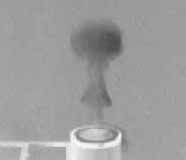 Mushroom cloud: vortex with conical fan structure. |
Figure 3 shows three successive firings. Note the almost identical position and shape of each of the initial conical fans. Note also the reduction in the diameter of the initial ejection between frames 2 and 3 in each sequence. This strongly suggests that the outer layer of the ejection is removed by drag, and that the initial fossil fan cloud is formed as this outer layer contracts to the axis behind the remaining core of the ejection and is wound into the forming vortex.
As above, it was found that the mass of the vortex increased as it moved away from the cannon, but no minimum was found at two meters. It was also noted that the trailing column of smoke was structured with additional less well formed fan clouds. It appears that both effects occur simultaneously. Additional outside air is added to the vortex and outer smoke laden layers are removed by drag.